Modeling the part
Using Freps to model
I was very interested in using Freps to model this assignment. Freps are very powerful tools for modeling complex parts that can be constructed by using mathematical signed distance functions to calculate the shape of a part. I used Axolotl, a plug in for grasshopper that creates the distance objects to model the parts using constructive solid geometry.
We were asked to model something that cannot be created using conventional subtractive manufacturing, so lattices and fills are the way to go. I used a gyroid function intersected with some pipes. These were the steps to model my part:
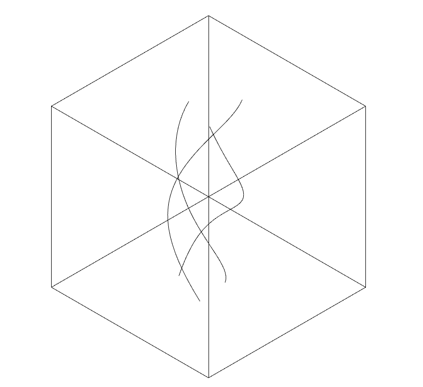
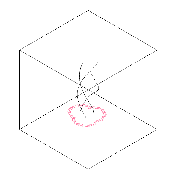
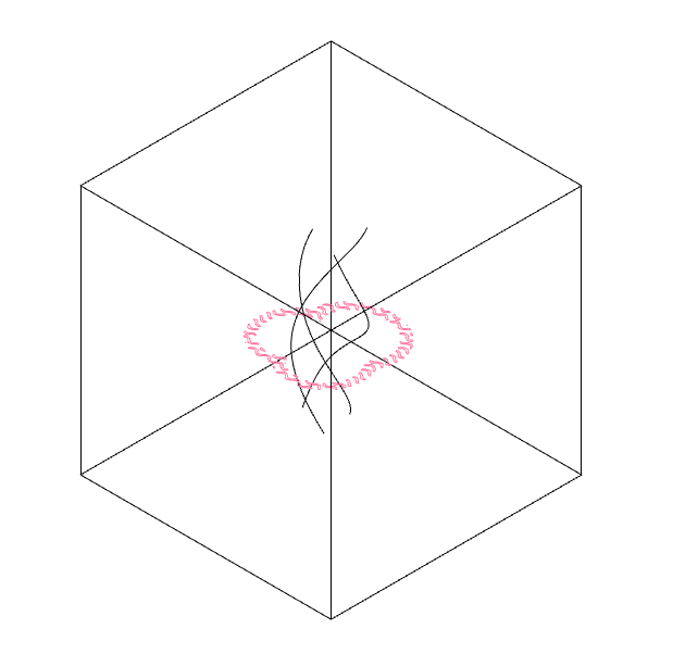
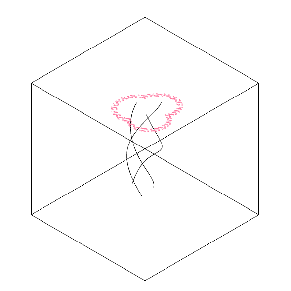
The first step was to model some curves in rhino using the curve command.
I made three curves that somewhat entwine with each other.
I also created a reference box, because Axolotl needs to work with predefined boundaries, or else it will completely freeze the computer.
This is because axolotl is calculating your geometry in a three-dimmensional grid of points, and the bigger the space it has to do it in, the more points it calculates and this gets messy very fast, so it's better to use small boxes as boundaries.
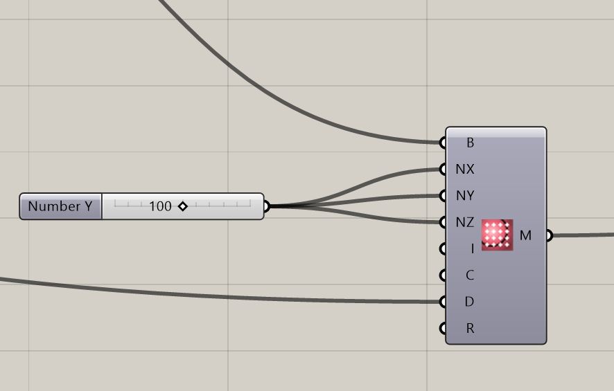
It's important to configure the bounding box and the isosurface settings correctly.
The pipes were modeled using simple curves, and thickened with Axolotl's pipe function in grasshopper.
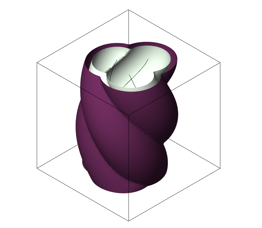
The pipes were then boolean unioned to create a single vase like object.
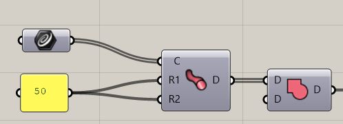
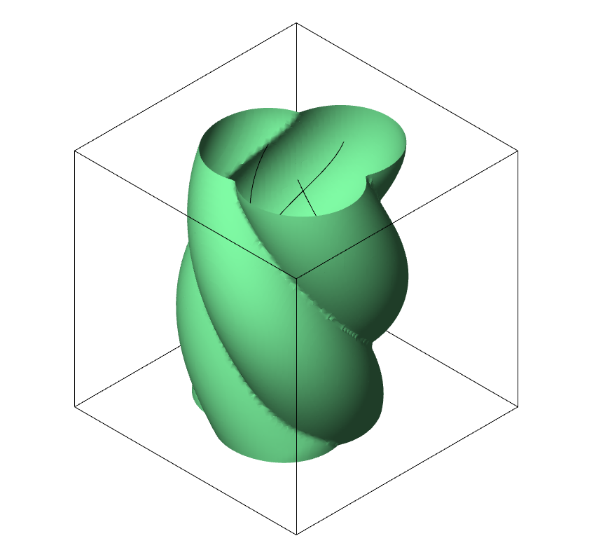
After boolean unioning the pipe objects, I used axolotl's shell component to create a hollowed out geometry.
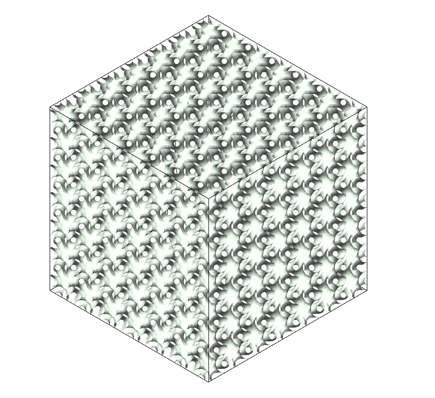
At the same time, I'm creating a gyroid object that creates this sine based surface that tiles the space. I also thickened it with the shell component, albeit with a smaller radius.
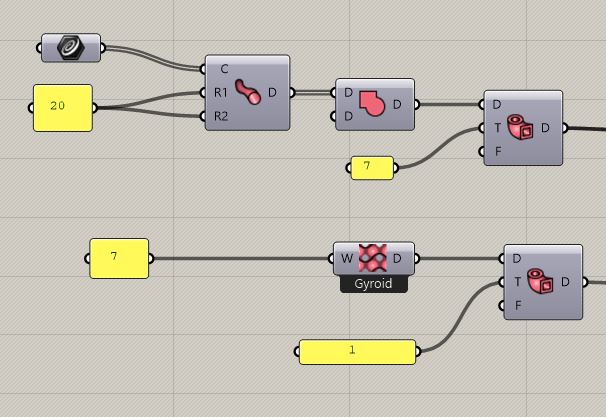
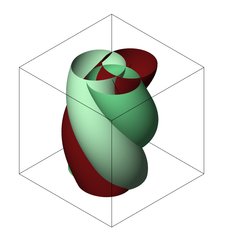
So now I have two objects, a thinkened pipe set, and a thickened gyroid object. What I'm going to do now is some interesting boolean operations.
I also made a slightlyshorter box which I used to intesect the gyroid with. This gave me a gyroid object that didn't touch the bounding box's caps.
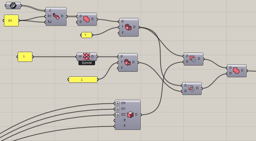
I'm subtracting the short box from the thickened pipes.
I'm intersecting the thickened pipes with the thickened gyroid
I'm uniting the slices that are left from the thickened pipes(at the top cap and at the bottom) with the intersection of the gyroit and the shortened pipes.
This gives me a thickened gyroid intersected with the thickened pipes, that also has a thin slice of the thickened pipes on the top and bottom.
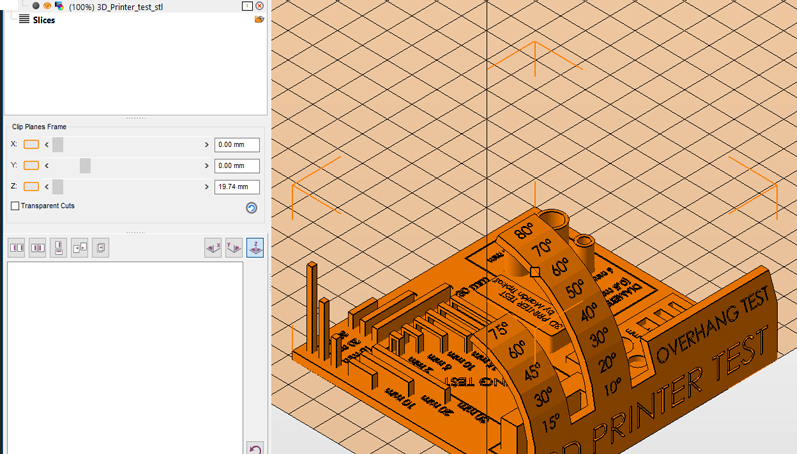
After all these operations, you can use different sections to see the model at a specific section plane:
The distance object is then fed to Axolotl's Meshing component IsosurfaceDistanceFunction that uses the marching cubes algorithm to mesh the object and bake it into rhino using right click and bake option.
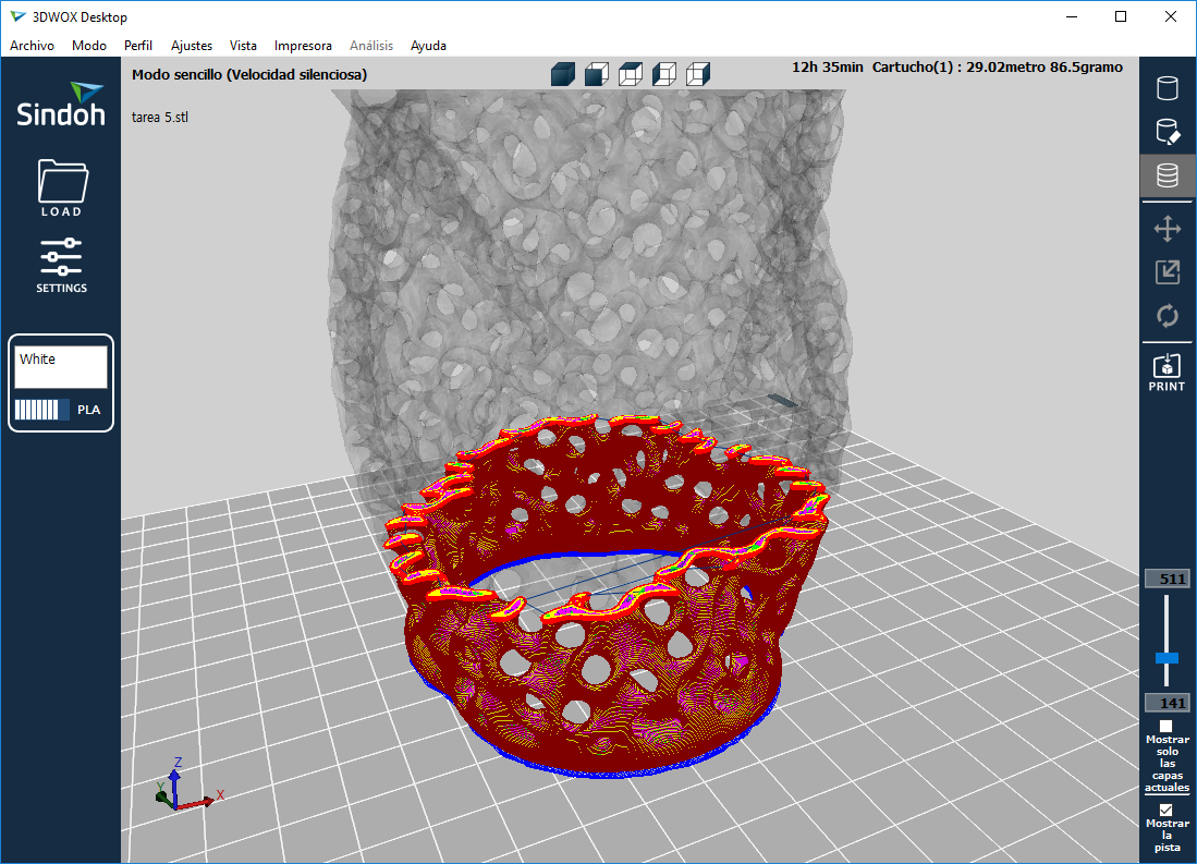
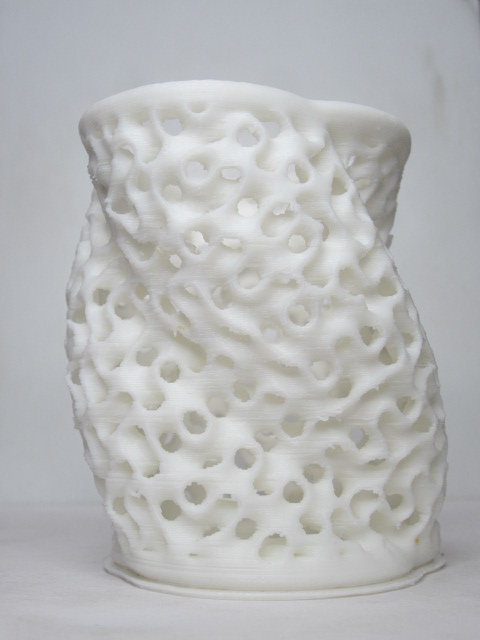
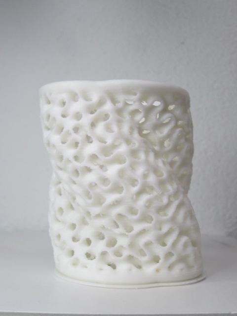
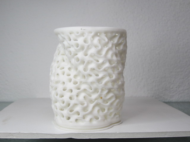
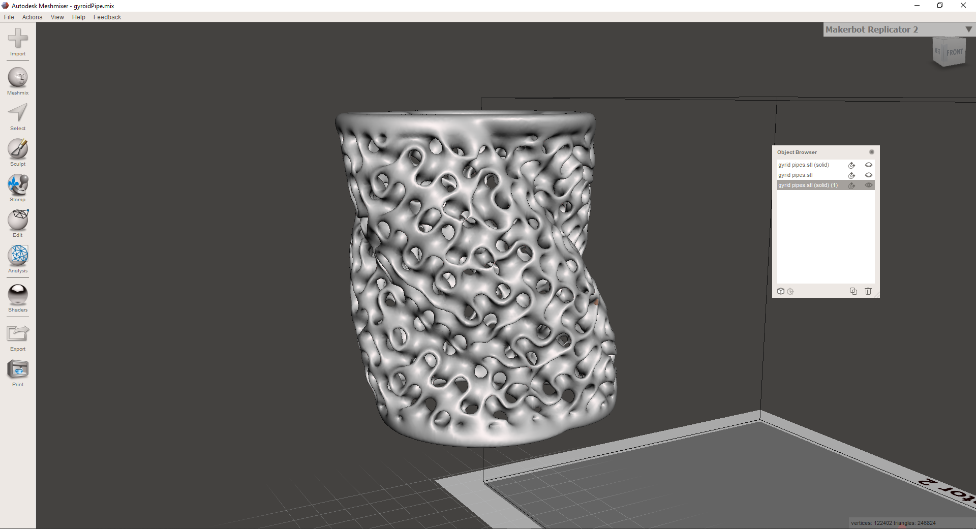
This workflow allows you to make pretty complex geometry that also is 3dprintable because gyroids generally are very printable because they have geometry that has very small overhangs. However, these geometries are very complex to model with other methods like breps, NURBS or meshes.
This is the reason that using CSG is in general a good idea for these types of strange objects.
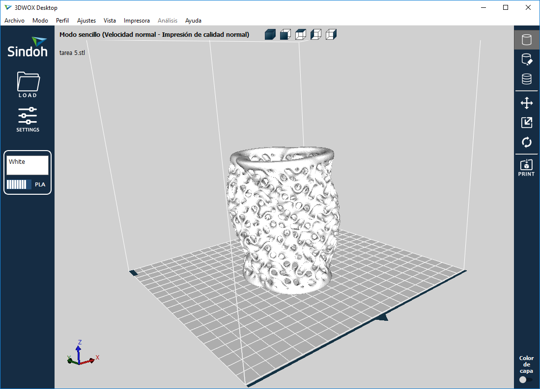
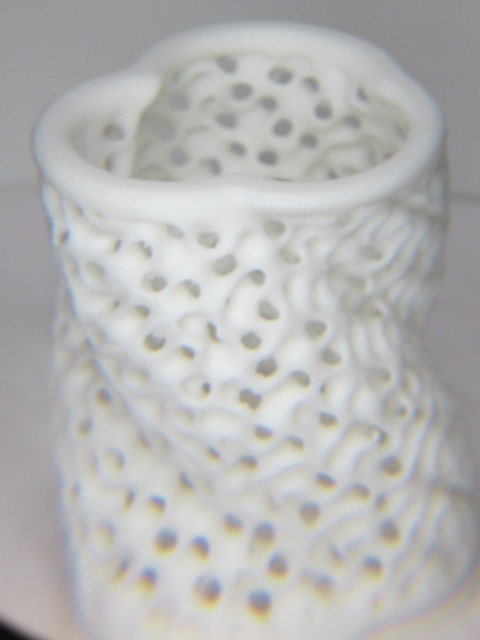
I then used meshmixer to clean up the isosurface model, which was also enhanced with a top and bottom solid as I explained.
back to top
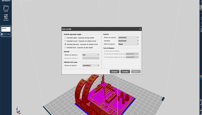
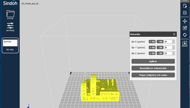
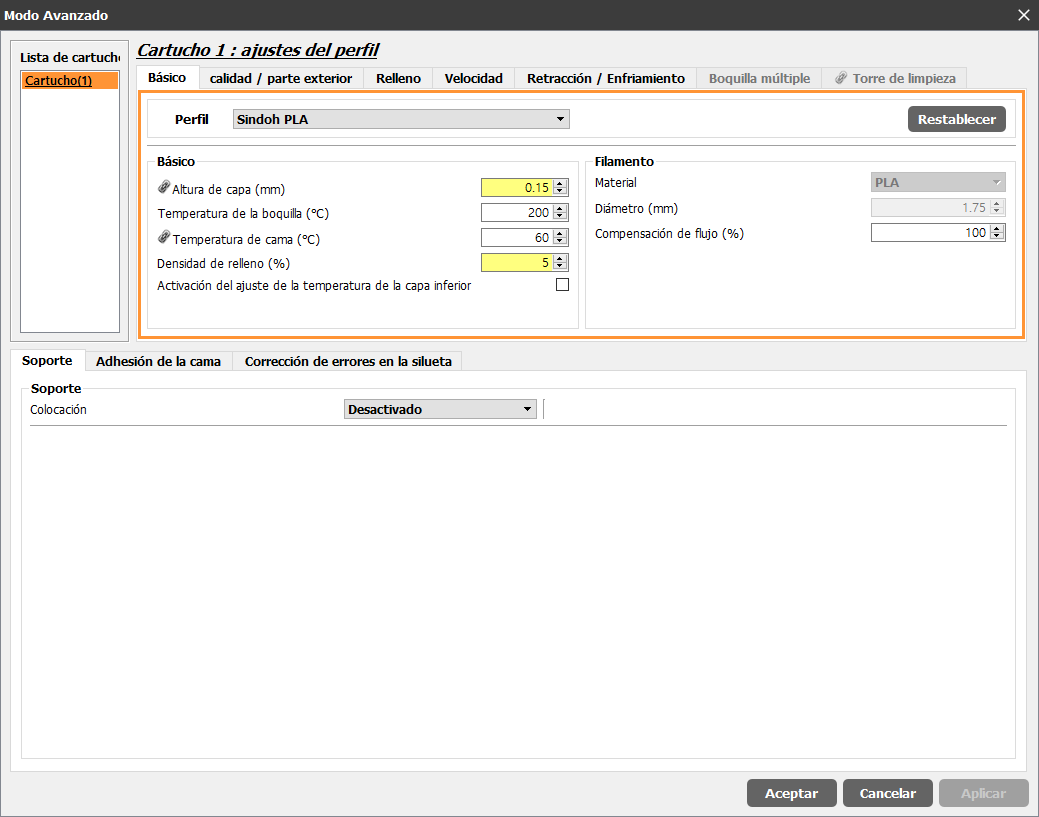
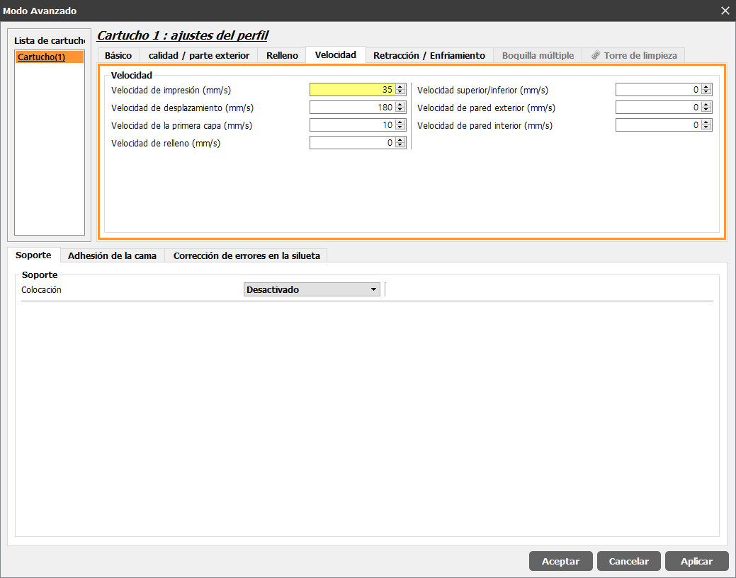
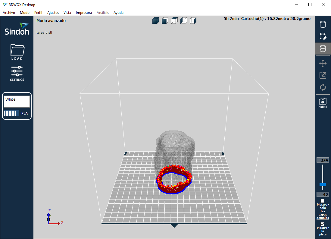
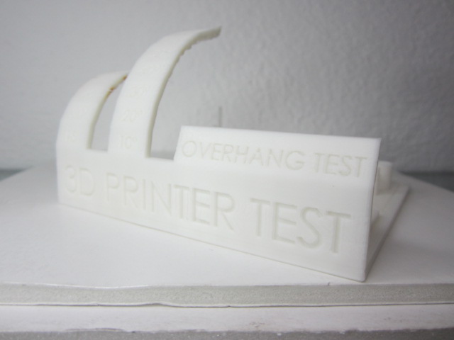 Sindoh
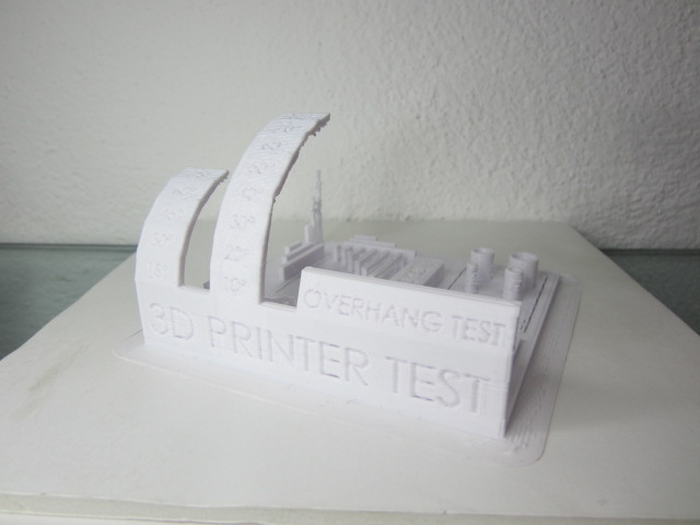 Rostock
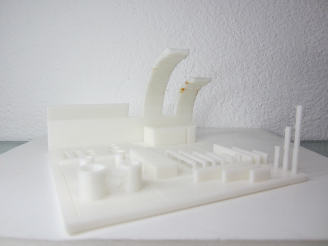 Sindoh
 Rostock